Product series
Contact us
Phone: +86-5065741650
Manager Wang
Email: 15065709046@163.com
Address: No. 10, District 1, 300 Changjiang Road, Yantai Economic and Technological Development Zone

Hydrogen separation/purification
A technology-based enterprise focusing on industrial gas separation and purification with gas separation membrane as the core technology
- Commodity name: Hydrogen separation/purification
Product details
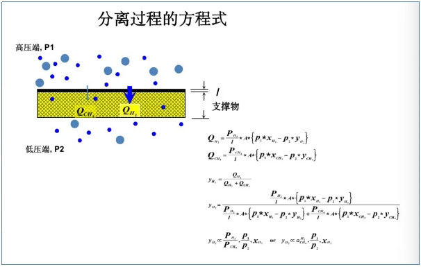
Gas Separation Membrane Working Principle
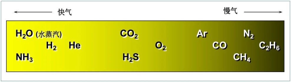
The working principle of a membrane separation system is to use a polymer (usually polyimide) film to selectively "filter" the feed gas to achieve separation. When a mixture of two or more gases passes through a polymer film, the differences in the dissolution and diffusion coefficients of each gas component in the polymer lead to different rates of permeation through the membrane wall. This allows gases to be divided into "fast gases" (such as H 2 O, H 2 , He, etc.) and "slow gases" (such as N 2 , CH 4 and other hydrocarbons). When the mixed gas is driven by the partial pressure difference of corresponding components on both sides of the membrane, faster gases with relatively high permeation rates preferentially pass through the membrane wall and are enriched on the low-pressure permeate side, while slower gases with relatively slow permeation rates are enriched on the high-pressure retentate side.
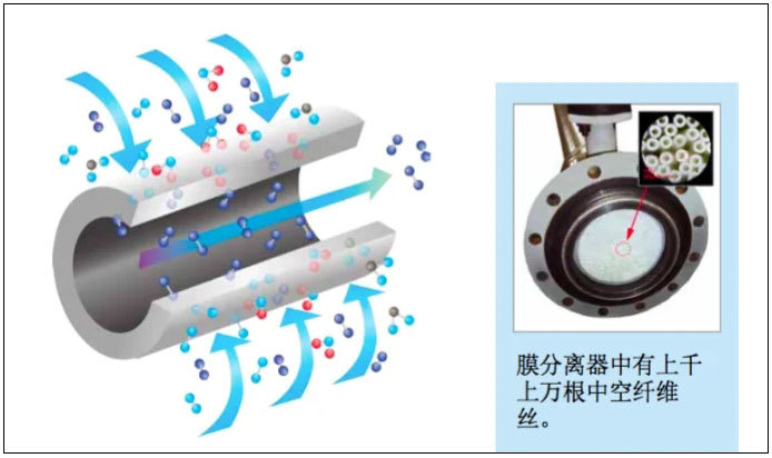
A typical membrane separator contains tens of thousands of fibers, sealed at both ends with epoxy resin. The ends of the fiber bundles are cut to expose the fiber pores at both ends, allowing gas to move from one end to the other. The fiber bundle is enclosed in a suitable casing. This casing protects the fibers and guides the gas flow correctly.
Gas molecules permeate through the thin wall of the membrane fiber driven by different partial pressures. Factors affecting permeability include solubility, diffusion rate, gas-polymer coordination, and the permeation rate of different gas component molecules. The greater the difference in permeation rates, the better the separation efficiency.
Gas Separation Membrane Performance Description
The core technology for all types of membranes used for gas separation involves modified polymer materials with different components. The principle of gas separation is the same, and the membrane's performance depends on each manufacturer's membrane material formula and production process. Therefore, different membranes have different separation efficiencies, different pressure resistances, and different service lives.
Generally, membrane performance can be described by gas production rate, recovery rate, and membrane lifespan:
1) Gas Production Rate: The amount of product gas that a single membrane can produce;
2) Recovery Rate: The percentage of the target product gas output relative to the content of the same component in the raw gas. A high recovery rate means less raw gas is required to obtain the same amount of product gas, leading to more economical operation;
3) Membrane Lifespan: The durability of the membrane is related to many factors, including the membrane material itself, the rationality of the separation system design, and operation and maintenance.
Membrane performance is also related to many factors such as the purity of the product gas produced, operating temperature, and operating pressure. For membranes used in air separation to produce nitrogen, the nitrogen recovery rate decreases as the operating temperature increases and slightly increases as the operating pressure increases, while the membrane's output increases with rising temperature and pressure. Therefore, membrane operation must be at a specific temperature and pressure to achieve optimal performance.
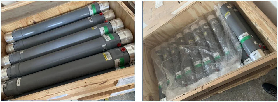
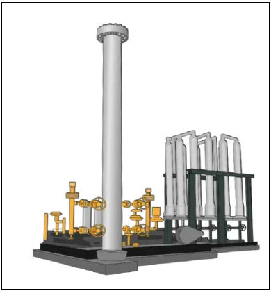
Gas Separation Membrane Structure - Hollow Fiber Membrane
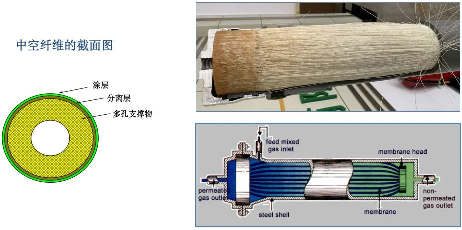
The core component of a membrane separation system is a membrane separator, similar to a shell-and-tube heat exchanger, where tens of thousands of tiny hollow fibers are cast into bundles and placed inside a pressure-bearing shell. After the mixed gas enters the separator, it flows axially along one side of the fibers. "Fast gases" continuously permeate through the membrane wall and accumulate on the other side of the fibers, exiting through the permeate gas outlet, while the retentate gas exits from the non-permeate gas outlet at the opposite end to the gas inlet.
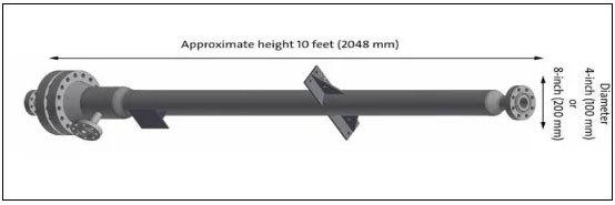
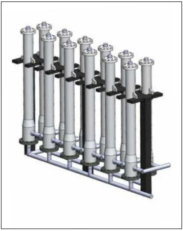
Gas Separation Membrane Structure - Membrane Separator Design and Arrangement
● Each membrane bundle is easy to install into the pressure vessel
● Unidirectional and durable sealing design for different pressures
● Axially packed membrane fibers (instead of tightly wound configuration)
● Pressure vessel conforms to: US standards, European standards, Russian standards, national standards, etc.
Membrane Separator Arrangement: Series and Parallel
● Series arrangement facilitates increasing or decreasing capacity, protecting downstream separators
● Parallel configuration can be used for high flow rates to reduce linear velocity inside the membrane separator
Gas Separation Membrane Structure - Hollow Fiber Membrane
1. External Pressure Type: Process gas treatment membranes - PO, P2, and P3 membranes, with over 30 specifications ranging from 2 to 8 inches.
Natural gas treatment membranes - material same as P2, with dozens of specifications ranging from 1 to 8 inches.
2. Internal Pressure Type: Air separation oxygen enrichment and nitrogen production membranes - P1, N1,2,3 and P3 membranes, with various specifications ranging from 1 to 8 inches.
Gas Separation Membrane System Features
Flexible: Operational flexibility of the membrane system when unexpected changes occur in plans or processes. To meet increased production, simply add more membrane separators. If production needs to be reduced, closing the separator's control valve can maintain the system's recovery rate and purity. Multi-faceted integration allows for different purities and flow rates from the permeate side.
Compact: Suitable for small or crowded plants with minimal on-site installation time, cost, and potential construction errors. Short on-site preparation time, requiring only simple concrete support pads and utilities. The membrane system is skid-mounted for easy relocation.
Effective and Economical: In most applications, membrane systems have high recovery rates, with efficiencies of 80-95% for hydrogen and hydrocarbons. The operating pressure of membrane systems is essentially the same as the pressure during refining, requiring no additional compression energy for the separation process. It consumes very little steam (for temperature control), instrument air, and purge nitrogen. The system is simple to start and stop, and the product gas does not require cooling or pretreatment.
Low Maintenance: Membrane separator groups have no moving parts to inspect, maintain, or replace. They are maintenance-free under proper design, installation, and operating conditions. However, attention should be paid to various process conditions during operation and some tolerable pollutants, such as liquid water, ammonia, hydrogen sulfide, hydrocarbons, and aromatics.
Long lifespan: Sound design and structure ensure a long lifespan in industrial applications.
Advantages
|
Basic Performance |
Cryogenic method |
Pressure swing adsorption method |
Membrane separation method |
|
|
Principle |
Separation medium |
|
Carbon molecular sieve |
Hollow fiber membrane |
|
Separation principle |
Liquefy air and separate it based on the different boiling points of oxygen and nitrogen. |
Pressure adsorption, pressure swing desorption |
Pressure permeation (different permeabilities) |
|
|
Energy consumption |
Energy-consuming components |
Compressor, expander, pressure pump, heating equipment |
Air compressor |
Air compressor |
|
Power consumption KWh/Nm3 |
>0.62 |
0.4-0.6 (average) |
0.4-0.6 (average) |
|
|
Cost Yuan/Nm3 |
>0.6 |
0.3 |
0.2-0.3 |
|
|
Equipment Performance |
Nitrogen production Nm3/h |
>500 |
<1000 |
10-5000 |
|
Nitrogen purity % |
99-99.999 (stable) |
98-99.9 (fluctuation) |
95-99.9 (stable) |
|
|
Nitrogen pressure MPa |
|
0.6 (fluctuation) |
0.6-1.8 |
|
|
Dew point ℃ |
-60--70 |
-40 |
-60- -70 |
|
|
Start-up time |
20 hours |
30 minutes |
Within 10 minutes |
|
|
Maintenance |
Many moving parts, large maintenance workload, requires regular overhaul. |
Valve replacement is easy to wear, frequent actions, there is maintenance workload and failure rate. |
No moving parts, very little maintenance and upkeep. |
|
|
Separation medium lifespan |
|
Domestic 5 years, imported 10 years. |
Hollow fiber 10 years or more. |
|
|
Equipment Parameters |
Process flow |
Complex |
General |
Simple |
|
Equipment status |
Fixed only |
Fixed only |
Fixed, mobile, indoor and outdoor. |
|
|
Plant area |
Maximum |
Smaller |
Small |
|
|
Cooling water |
A lot |
None |
None |
|
|
Height |
Local 12 meters |
4-10 meters |
4 meters |
|
|
Electrical capacity |
Maximum |
Smaller |
Minimum |
|
|
Dimensions |
Largest volume |
Smaller volume |
Smallest volume |
|
|
Capacity expansion |
Difficult to expand capacity |
Difficult to expand capacity |
Separation membranes are assembled in parallel, easy to expand capacity. |
|
|
Random start/stop |
Cannot |
General |
Very easy |
|
|
Basic investment |
High |
Low |
Lower |
|
|
Operators |
Requires dedicated operators |
No dedicated operators required |
No dedicated operators required |
|
|
Special requirements |
Requires professional installation, high installation cost |
None |
None |
|
|
Operating costs |
Higher |
General |
Lower |
|
Applicable industries and scenarios for gas separation membranes
Hydrogen recovery and separation from ammonia purge gas
Hydrogen recovery and separation from refinery gas
Hydrogen purification from reformed gas
H 2 CO ratio adjustment and CO purification
Hydrogen recovery from methanol tail gas
Natural gas dehydration and acid gas removal (including carbon dioxide and hydrogen sulfide)
Ammonia purification and recovery from LNG flash gas
Helium purification and recovery from coal bed methane
Helium purification and recovery from various feed gases
Application of membrane separation systems in ammonia plants
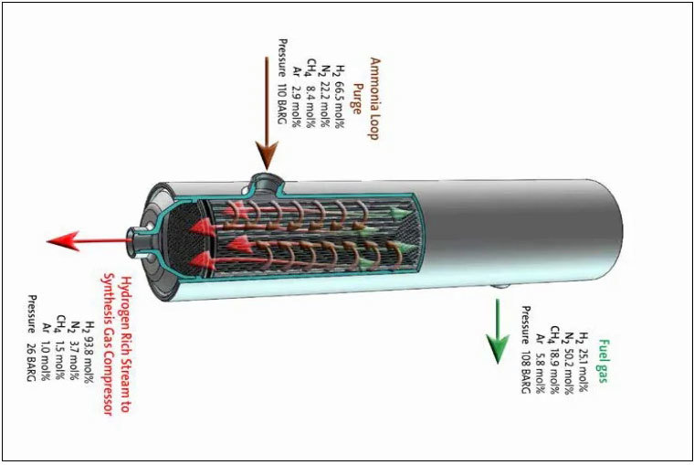
Hydrogen recovery from ammonia purge gas
In the process of ammonia synthesis in a catalytic reactor, the components include hydrogen, nitrogen, and inert gases such as methane and argon. Ammonia conversion is not complete in the first stage of synthesis, and the process requires circulation, leading to the accumulation of inert gases and the release of purge gas which is introduced into the synthesis gas to produce ammonia via the catalytic reactor. The composition of the synthesis gas is hydrogen, nitrogen, and inert gases such as methane and argon; ammonia conversion is not complete in the first stage of synthesis, so a circulation reaction is needed, but this can lead to the accumulation of inert gases and purge. This purge gas contains a large amount of synthesis gas components, including ammonia (unliquefied). If not recovered, this will be a waste of ammonia cost. The membrane system can process this purge gas, recovering ammonia as product gas and returning hydrogen to the synthesis gas loop. The system usually includes a water washing tower to absorb ammonia. The membrane system can recover 90% of the hydrogen in this purge gas, increasing ammonia production. The system can be easily adjusted to meet the needs of production fluctuations.
Application of membrane separation systems in the petrochemical industry
In petrochemical plants, membrane systems recover hydrogen and adjust synthesis gas components for optimal results. High-pressure petrochemical gas is introduced into the membrane separator, and the membrane system uses selective permeability to recover and purify valuable hydrogen or separate usable inert by-products through non-permeation.
Membrane system applications in petrochemical processes include: hydrogen recovery from methanol plant purge gas, synthesis gas ratio adjustment, CO purification, purge gas from hydrogenation processes, and hydrogen recovery from PSA desorption gas.
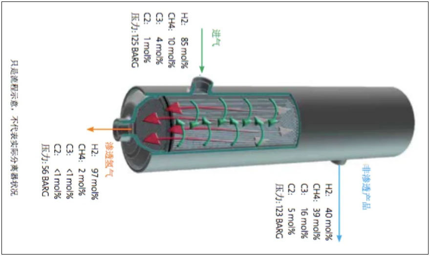
Hydrogenation process purge gas
The hydrogen recovered by the membrane system can be used in hydrogenation processes and other applications. The membrane system is designed to increase hydrogen purity from 60-70 mol% to 85-95 mol%, with a recovery rate exceeding 90%. If the purity requirement is fluctuating, the membrane system can adapt to a wide range of instantaneous flow rate changes to stabilize fluctuations in other hydrogen recovery systems while ensuring a high recovery rate.
H2 recovery from PSA desorption gas
By compressing the PSA desorption gas, the separator can recover more than 90% of the hydrogen and concentrate the remaining tail gas.
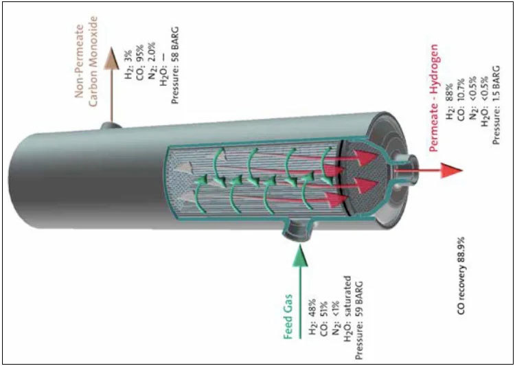
CO collection (purification of CO from feed gas containing hydrogen)
In this application, the membrane system can produce 85% pure CO in a single stage. If higher purity CO is required, a two-stage system and reciprocating compressor will improve the effect, increasing the CO product purity to 95% or higher. The membrane separator can remove water like hydrogen, so the CO gas can be used without drying.
How membrane separators work in petrochemical plants
Removing impurities from industrial gases and recycling valuable gases to save costs. Membrane separation systems allow process gases to be mixed for extended periods, maximizing circulation to achieve the required reaction amount.
Hydrogen recovery from methanol purge gas
Synthesis gas produces methanol through catalytic reaction. The components of synthesis gas are hydrogen, CO/CO2, and inert gases such as methane, nitrogen, and argon; methanol conversion is not complete in the first stage of synthesis, so the process requires circulation to form a loop. This process causes the accumulation and release of inert gases.
This type of purge gas contains a large amount of synthesis gas components, including methanol (unliquefied). The membrane system can process this purge gas, separating methanol as a product and allowing hydrogen to go to the synthesis gas recycle loop. The system usually includes a water washing tower to clean and absorb the released methanol.
H2/CO synthesis gas ratio adjustment (synthesis gas)
The separator adjusts the H2/CO ratio in the ethanol synthesis gas. Membrane separators are well-suited for this application, and the pressure of the treated product gas is essentially the same as the pressure of the synthesis gas loop, and the H2/CO ratio can easily meet the requirements of this specific process.
Application of membrane separation systems in the refining industry
Many processes in the refining process use membrane systems, from refining tail gas to dry gas recovery, membrane systems show extraordinary operability and economic value. Membrane systems use the principle of selective permeation separation to process pressurized process gases, including hydrogen purification, inert byproduct removal, and hydrogen recovery.
Membrane systems are key equipment for hydrogen recovery in refinery hydrogenation processes. They can inhibit the accumulation of inert gas components in the hydrogen recycle loop, meaning that only a small amount of fresh hydrogen is needed to maintain the hydrogen balance in the system, thus significantly reducing the operating costs of the system. General membrane systems require a pretreatment section to remove entrained liquids from the feed gas and heat the membrane gas. Key process parameters include: pressure, temperature, impurity removal, and membrane permeation surface area (determined by the number of separators determined during system design).
Different configurations of membrane separators can achieve suitable hydrogen purity and recovery rates. Membrane separation systems can be customized according to the user's specific operational and capacity requirements.
High-value hydrogen is required for hydroprocessing in petroleum refining. Hydrogenation furnaces (rich hydrogen gas containing inert gases such as methane and high-carbon hydrocarbons) can produce high-pressure tail gas. The hydrogen with "inert gas" removed can be recycled, and adding a small amount of new hydrogen can meet the requirements of the hydrogenation process.When the feed gas enters the separator, the fast gas (hydrogen) permeates the membrane wall side of the hollow fiber bundle faster than other heavy components, and returns to the hydrogenation process together with the new gas. The gas that does not pass through the membrane (non-permeate) also contains less than 30% hydrogen, but contains methane and high-carbon hydrocarbons, which are transported to the fuel network. These hydrocarbons can be recovered using turbo expanders or cryogenic systems.
Hydrogen recovery from relief gas
Using membrane systems, the relief gas in the hydrogenation process can be purified to 92-98%, and the recovery rate can reach 85-95%. Even the tail gas from catalytic cracking units containing 20-30% hydrogen can be upgraded to 70-90% with a single-stage membrane separator or to 95% with a two-stage membrane separator.
Removal of inert gases from recycled hydrogen
One method to improve the processing capacity of hydroprocessing or hydrocracking units is to recover high-purity gas from relief gas as hydrogen supplementation. Another method is to remove inert components from the recycle loop. The method of removing inert gases from the reactor using a membrane separator to improve the purity of hydrogen in the loop is better than simply supplementing with new hydrogen. The method of removing inert by-product gases allows operators to adjust the hydrogenation reactor to accommodate a wider range of feedstock and product performance without wasting hydrogen.
Fine-tuning the hydrogen chain
By increasing the hydrogen partial pressure in the feed gas, membrane systems can extend the catalyst life of the hydrogenation reaction. The increase in feed gas purity allows existing reactors to have higher yields or efficiency. In newly installed hydrogenation systems, membrane systems can recover hydrogen from both low-purity fuel gas and from catalytic reforming tail gas.
Hydrogen production unit (methane steam reforming unit)
Using membrane systems to recover high-purity hydrogen from the feed gas of the methane steam reforming unit eliminates production bottlenecks. As hydrogen is removed, more hydrocarbons enter the methane steam reforming unit, thus increasing hydrogen production.
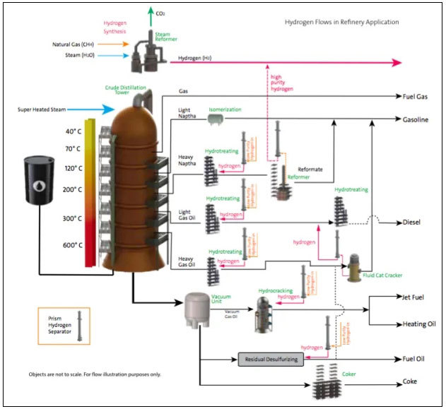
This flow chart shows the various processes of hydrogen application in petroleum refining, with natural gas and superheated steam as the raw materials for hydrogen production. Because each hydrogenation reaction is not complete, the product tail gas of each hydrogenation process contains hydrogen. The hydrogen-containing tail gas can be recovered and purified using a membrane system. Recycled hydrogen is therefore used to supplement or partially replace the new hydrogen supply.
Keywords:
Hydrogen separation/purification


Contact us
No. 10, District 1, 300 Changjiang Road, Yantai Economic and Technological Development Zone


Leave a message
*Note: Please fill in the information accurately and keep the communication open. We will contact you as soon as possible.
SAF Coolest v1.2 设置面板 GAGSE-ZGYF-JSAZE-ZSE
无数据提示
Sorry, there is currently no content in this section!
You can view other sections or return to theHomepage